We developed a direction system for assisting the work in a real world from a distant site. The system consists of
several sets of a camera, pro jector and PC connected via network each other. At first, the 3-D shape of the ob ject
is measured using pattern light pro jection method and sent to the distant PC. A supervisor at the distant site can
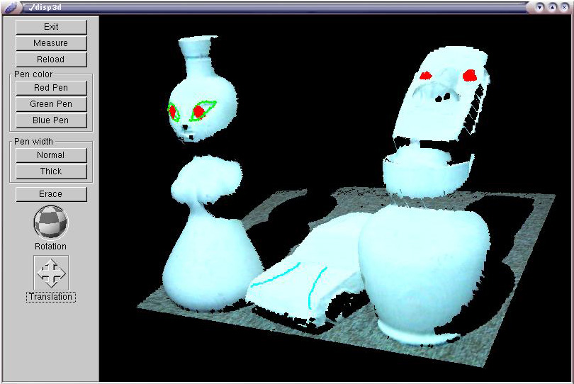
observe the CG of the ob ject from any viewpoint and draw annotation figures on the CG. The figures of the direction
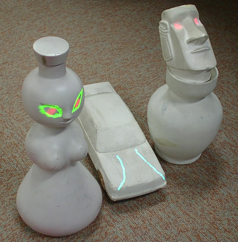
message are sent to the real field and pro jected onto the ob ject using pro jectors. The pro jected figures are well aligned
geometrically because the all cameras and pro jectors are calibrated with single reference ob ject. The worker is free
from any wearing equipment, ex. HMD, and multi pro jectors avoid the problem of occlusion by the worker body.
Direction method for the task of alignment of both existing and new ob ject is also implemented.
 video 1 : Whole shape of the object is measured and then displayed on the monitor in front of the director.
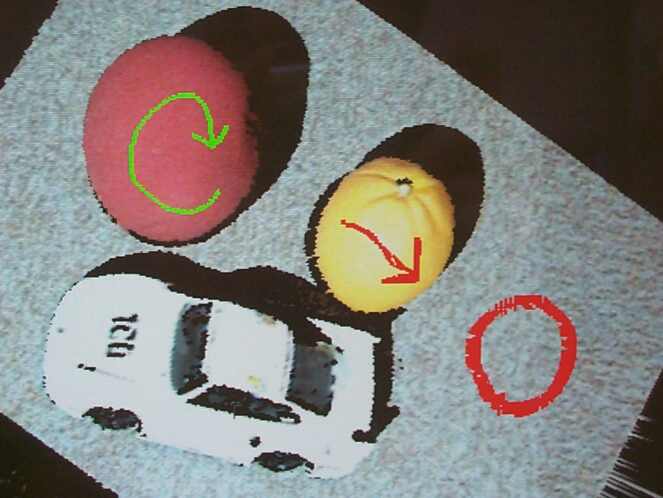
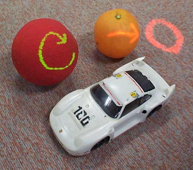
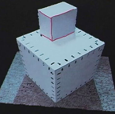
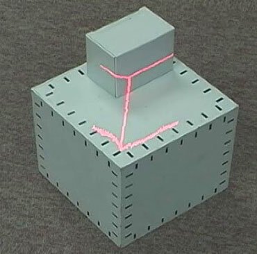
2. video 2 : The director will simply draw some figures on the CG of the object for direction. The drawn figures are projected onto the real object immediately.
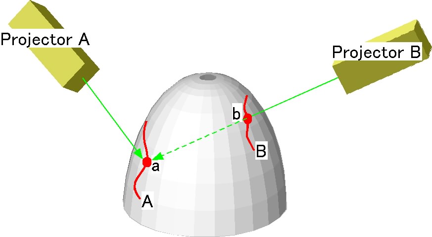
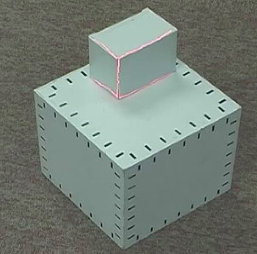
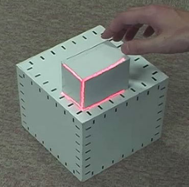
3. video 3 : Since we used two projectors, the projected light partly duplicates. It is preferable when the light is occluded by the worker's body.
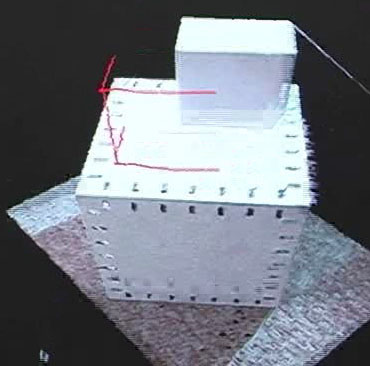
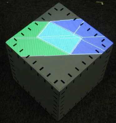
4. video 4 : Specifying the displacement of the existent object.
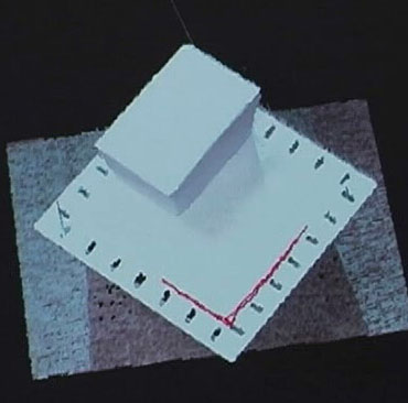
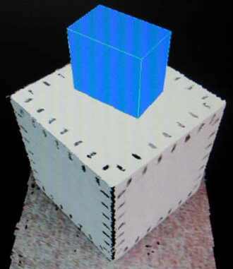
5. video 5 : Specifying the position of the object to place.
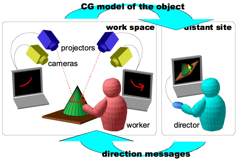
Distant communications via internet are now remarkably evolving in the sense of the both quality and quantity. Especially, visual information is very important for dealing with real objects and it enables a distant cooperation of spatial work such as assembly or construction. In the field of industrial design, networked CAD and VR system are used for handling a computational shape model, but in some cases real carving work with a clay model is easy and intuitive. For that reason, telecommunication and cooperation system for supporting a work with existent object is demanded. In this paper we propose a system for directing and advising the worker with a real object from distant site using projectors. In the following, we call the space with a worker and a real object "work space" and the place of the director "distant site".
The simplest visual tele-direction system is a popular teleconference system. This system makes it easy to know the situations of the work space, but the indication from the director is not easy to understand by the worker. This problem is caused by the absence of the object at the distant site, and the director can do nothing to express his intention.
An improved visual teleconference system against such communication problem has been proposed. The HyperMirror [1] is a system which simulates a mirror electronically, but contrary to the actual mirror the director at a distant site is also reflected in a mirror. Using this system, the director can use a gesture of pointing the finger at the object in a mirror. However, the worker must compare the real object and the images shown on a mirror. If the worker concentrates on the object, the gesture by the director may be ignored.
As described abobe, it is important that the direction message is well aligned to the object geometrically. The technological solution for such consistency problem may belong to the area of Virtual Reality research. HMD based work direction systems [2][3] have an advantage of large applicable space and worker can work around the object freely. However, either position sensors or markers must be attached to the HMD to archieve the consisytency between displayed indication figures and the real object seen through the HMD. The narrowed view and the latency of the displayed figures from the real object must be also concerned in the sense of safety, and the weight of the HMD and its harness strains the worker.
Techniques of the augmented reality are not restricted to the device between eyes and the object as mentioned above. Controlling the incident light which illuminates the object also changes its appearance, and now popular projectors for presentation are enough flexible to achieve this task well. Several studies about projection based MR system for displaying varied virtual texture on a object have been carried out[4]. The advantages of this method is as follows: (1) The overlayed image does not move along with the motion of the viewpoint, (2) 3-D object can be also handled, (3) the workers do not need to wear any equipments, (4) multiple users can use, (5) the workers can walk around the object freely. Since we valued these advantages, we developped a tele-direction system using projectors with eliminated some weak points. We utilized multiple projecters to avoid the problem of occlusion of the projected light by workers' body. Projection onto the backside of the object can be also possible. Contrary to using HMD, the projection based MR can not show a image floating in the air, but in practice it makes no difference because of the sofisticated visual function of human.
The construction of the projector based tele-direction system is shown in figure 1. Several sets of a camera, projector and PC are placed at the work space. Each set of a camera, projector and PC forms a rangefinder based on active triangular measurement method. At first, the 3-D shape and texture of the object at the work space is measured using the cameras and projectors. The data is sent to the PC at the distant site and shown as a CG on a display. The director can observe the CG of the object from any viewpoint and simply draw direction messages on the CG object at any time. The drawn figures are simultaneously projected onto the object. The followings are detailed overview of the system.
|
|
| (a) | (b) |
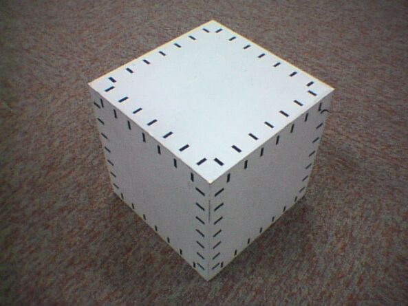
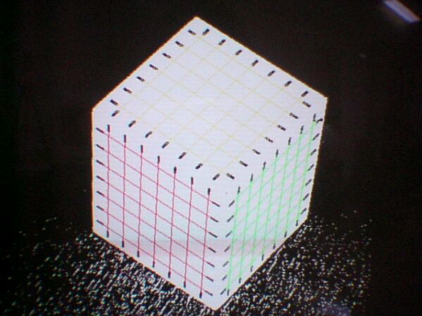
To calibrate the projector, several horizontal and vertical graycoded light patterns are projected onto the reference cube. By analyzing the captured images, many sets of coordinates on a projector (x_p, y_p) and camera (x_c, y_c) are collected and the following 3 x 4 projector parameter matrix P is calculated.
Based on these system parameter matrices C, P, the 3-D shape of the object can be measured using graycode projection method. Since we used multiple cameras and projectors, all cameras and projectors must be calibrated with a common world coordinate. It is easily achieved because the reference cube we used has reference markers at each surface. The time to measure the object is less than 3 seconds, and the calculation time of the rangeimage is about 5 seconds. Measured range image is sent to the PC at the distant site with the color texture images taken simultaneously.
|
|
| (a) | (b) |
As described in section 2.1, the coordinates of the points must be represented in a world coordinate system (X,Y,Z) to project the indication figures onto the object precisely. However, the pointing by mouse only enters the 2-D coordinate on a screen, therefore it must be transformed to the world coordinate. We use the depth buffer of the OpenGL to acquire the 3-D coordinate. At first, the value of the depth buffer at the point of the mouse cursor is read. Then, the perspective projection matrix set in the graphics hardware is read out and calculate the inverse transformation. Finally the inverse transformation is applied to the set of screen coordinate and the value of the depth buffer. The calculated points in the world coordinate are sent to the all PCs at the work space, and transformed to the projector coordinates (x_p,y_p).
Prior to enter the displacement of the object, the director must specify the part of the object to move. As shown in figure 5(a), the director traces the feature lines as edges on a CG model. The traced lines are transformed to the sequence of 3-D points immediately, and it can be moved with certain displacement using keyboard entry. The drawn line is projected onto the object at the work space and moved simultaneously. As shown in figure 5(e), the projected lines are skewed if the object is not planar, but the worker can move the object as intended easily(figure 5(f)).
| 
| 
(a)
| (b)
| (c)
| 
(d)
| (e)
| (f)
| |
(movie)
| 
| 
(a)
| (b)
| (c)
| |
(movie)